Using the wiring specifications that came with your analog sensor, connect to the proper pins using the diagram below. You will need to follow the on-device data logging instructions above to properly display the input.
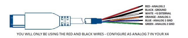
NOTE: Do not connect any device that exceeds 5 volts to the analog port or permanent damage to the adapter can occur.
Once this is setup, you need to go to the "On Device and Data-logging and Monitoring Menu"
This menu accesses the Monitoring and Data Logging feature. This menu is also used when collecting data from the analog input on the device.
1. With your key out of the ignition, connect your device to the OBDII port to power on your X4.
Using the down arrow, highlight “Gauges/Datalog” and select it by pressing the center button on
the keypad.
2. Turn the key to the ON position, and use the left arrow to select “Configuration” at the bottom of
the screen.
3. Select your vehicle type from the list of Datalog Files provided using the down arrow key and
selecting “Continue”.
4. See “Editing a Gauge” and “Editing Gauge Layout” to configure your display.
5. Once you have your layout and gauges selected, start your vehicle.
6. To record, press the center button on the keypad.
7. To stop/end your datalog, press the left or right button and select “Stop Datalog”
Editing a Gauge
To edit a gauge you will use the up or down arrows to highlight the gauge/parameter you would like to change, then press the center button on your keypad.
a. Item: Here you will find a list of parameters that are preloaded on your device. You can find the Analog Inputs at the bottom of this list.
b. Unit: Based on the item you have chosen from the list, the unit will change to the corresponding unit of measure. If you are choosing an Analog Input, you will need to select the appropriate preset equation based on your analog source.
Available Equations: SCT has preset the most common equations as a list to choose from:
- V (this would be Voltage)
- SCT EGT ˚ F
- PLX EGT ˚ F
- AEM X-WIFI EGT ˚ F
- SensorConnection EGT ˚F
- ExhaustGasTech EGT ˚F
- LM1
If you need to monitor more than two gauges at a time then you will need to change your layout.
You may only monitor a maximum of 8 parameters at a time.
1. From the Main Gauge display, press the left or right arrow button once.
2. Scroll down to highlight “Select Gauge Layout” and select it.
3. Highlight the layout you want to view and press the center button.
4. To edit the new layout use the instruction under “Editing a Gauge” above.
- TW 2A0
- PLX
- LC1
- AEM
- AFM1000
- G100
- Dyno Jet WBC
- GM 1Bar MAP
Editing Gauge Layout
If you need to monitor more than two gauges at a time then you will need to change your layout. You may only monitor a maximum of 8 parameters at a time.
1. From the Main Gauge display, press the left or right arrow button once.
2. Scroll down to highlight “Select Gauge Layout” and select it.
3. Highlight the layout you want to view and press the center button.
4. To edit the new layout use the instruction under “Editing a Gauge” above.